
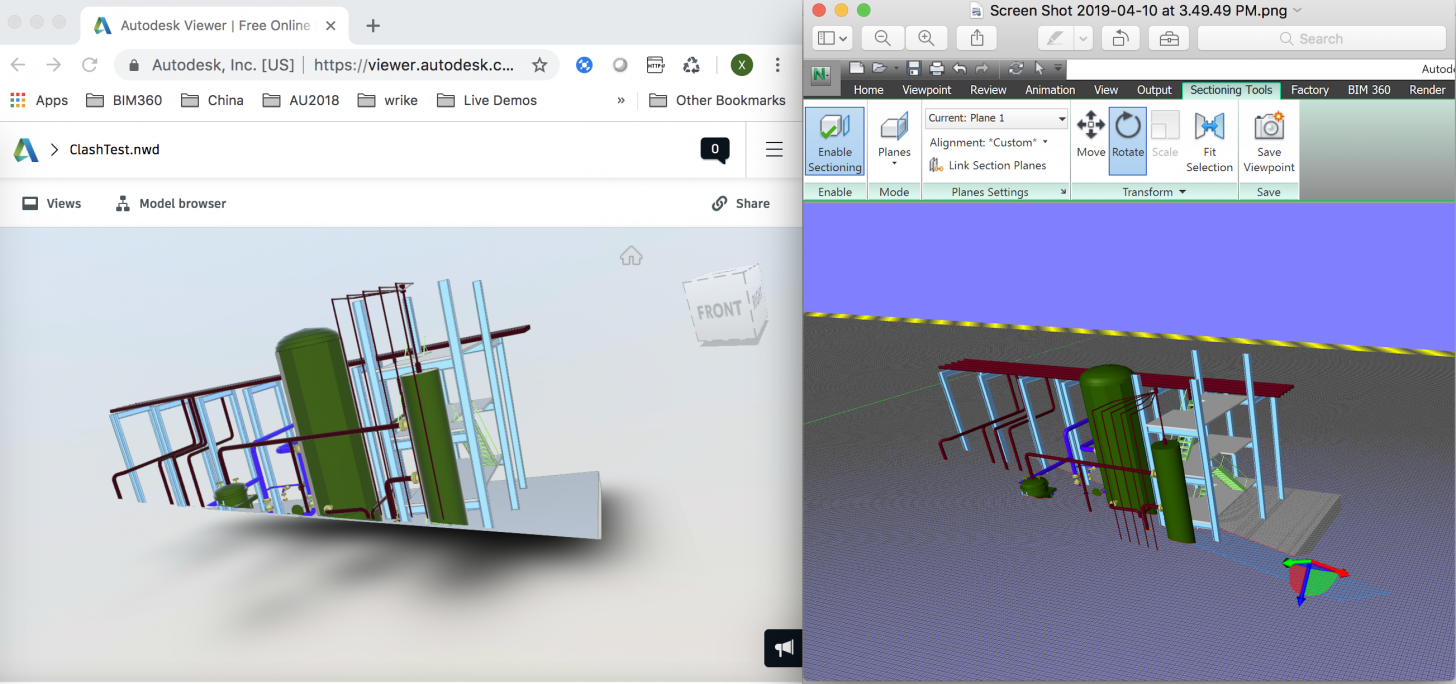
Navisworks provides the ability of Sectioning to place plane or box to create cross sections on the model in a 3D workspace. By saving and export SavedViewpoints, we can get the params of the sectioning planes. The below is one demo XML. It contains the sectioning planes collections (6 planes). Each item indicates if this plane has been enabled, and corresponding param: direction and distance. This XML also contains data of camera of this viewpoint, which you can map with Forge Viewer (please check Load XML of Navisworks Saved Viewpoints to Forge Viewer Cameras).
<?xml version="1.0" encoding="UTF-8" ?>

<exchange xmlns:xsi="http://www.w3.org/2001/XMLSchema-instance" xsi:noNamespaceSchemaLocation="http://download.autodesk.com/us/navisworks/schemas/nw-exchange-12.0.xsd" units="m" filename="ClashTest.nwd" filepath="\\Mac\Home\Documents\01-Models">
  <viewpoints>
    <view name="MySectionView" guid="eeb13f7c-eeef-4491-a8b4-e384208b5522">
      <viewpoint tool="autocam_orbit" render="shaded" lighting="headlight" focal="581.3223714544" linear="49.2732722032" angular="0.7853981634">
        <camera projection="persp" near="129.8380991414" far="1233.7761402178" aspect="1.1584699454" height="1.3867859357">
          <position>
            <pos3f x="2079.6305746691" y="1800.7915146308" z="299.9883502333"/>
          </position>
          <rotation>
            <quaternion a="0.1299778395" b="0.5497428319" c="0.8030201205" d="0.1898611757"/>
          </rotation>
        </camera>
        <viewer radius="0.3000000000" height="1.8000000000" actual_height="1.8000000000" eye_height="0.1500000000" avatar="construction_worker" camera_mode="first" first_to_third_angle="0.0000000000" first_to_third_distance="3.0000000000" first_to_third_param="1.0000000000" first_to_third_correction="1" collision_detection="0" auto_crouch="0" gravity="0" gravity_value="9.8000000000" terminal_velocity="50.0000000000"/>
        <up>
          <vec3f x="0.0000000000" y="0.0000000000" z="1.0000000000"/>
        </up>
      </viewpoint>
      <clipplaneset linked="0" current="3" mode="planes" enabled="1">
        <range>
          <box3f>
            <min>
              <pos3f x="1.0000000000" y="1.0000000000" z="1.0000000000"/>
            </min>
            <max>
              <pos3f x="0.0000000000" y="0.0000000000" z="0.0000000000"/>
            </max>
          </box3f>
        </range>
        <clipplanes>
          <clipplane state="default" distance="0.0000000000" alignment="top">
            <plane distance="1051.6400000000">
              <vec3f x="0.0000000000" y="1.0000000000" z="0.0000000000"/>
            </plane>
          </clipplane>
          <clipplane state="default" distance="0.0000000000" alignment="bottom">
            <plane distance="0.0000000000">
              <vec3f x="0.0000000000" y="1.0000000000" z="0.0000000000"/>
            </plane>
          </clipplane>
          <clipplane state="default" distance="0.0000000000" alignment="front">
            <plane distance="1245.8350000000">
              <vec3f x="0.0000000000" y="1.0000000000" z="0.0000000000"/>
            </plane>
          </clipplane>
          <clipplane state="enabled" distance="0.0000000000" alignment="back">
            <plane distance="-1358.1803635286">
              <vec3f x="-0.0000000000" y="-1.0000000000" z="-0.0000000000"/>
            </plane>
          </clipplane>
          <clipplane state="enabled" distance="0.0000000000" alignment="left">
            <plane distance="1148.9864366591">
              <vec3f x="1.0000000000" y="0.0000000000" z="0.0000000000"/>
            </plane>
          </clipplane>
          <clipplane state="default" distance="0.0000000000" alignment="right">
            <plane distance="-1148.9864366591">
              <vec3f x="-1.0000000000" y="0.0000000000" z="0.0000000000"/>
            </plane>
          </clipplane>
        </clipplanes>
        <box>
          <box3f>
            <min>
              <pos3f x="1.0000000000" y="1.0000000000" z="1.0000000000"/>
            </min>
            <max>
              <pos3f x="0.0000000000" y="0.0000000000" z="0.0000000000"/>
            </max>
          </box3f>
        </box>
        <box-rotation>
          <rotation>
            <quaternion a="0.0000000000" b="0.0000000000" c="0.0000000000" d="1.0000000000"/>
          </rotation>
        </box-rotation>
      </clipplaneset>
    </view>
  </viewpoints>
</exchange>
Forge Viewer also provides the ability to set sectioning planes. This blog tells the basic usage: https://forge.autodesk.com/blog/viewer-setcutplanes. In some workflows, we need to map the planes of Navisworks viewpoints to Forge Viewer. However, using the same parameters from Navisworks XML, the planes are not correct in Forge Viewer. The sectioning results are not same to those in Navisworks. After some investigation, I found some tricks with the mapping.
One source model might probably be designed far from the WCS origin. The sectioning planes align with the XYZ of the origin. e.g. in the sample model ClashTest.nwd, Plane 1 is enabled. It aligns to Y+ axis. The plane normal is [0,1,0]. Only the Y+ (0,1,0) value can affect the sectioning. Current value is 1500. After export the viewpoint, the param in XML will be:
 <clipplane state="enabled" distance="0.0000000000" alignment="top">
            <plane distance="1500.0000000000">
              <vec3f x="0.0000000000" y="1.0000000000" z="0.0000000000"/>
            </plane>
 </clipplane>
If the plane is rotated and becomes to custom, the related param will look like:
<clipplane state="enabled" distance="0.0000000000" alignment="custom">
            <plane distance="886.2418151801">
              <vec3f x="0.1368226246" y="0.4334009763" z="0.8907542664"/>
            </plane>
  </clipplane>
In any case, the distance in XML = vec3f.x * (X value in UI ) + vec3f.y * (Y value in UI) + vec3f.z * (Z value in UI)
In Forge Viewer, after the model is placed by setting center of bounding box of the model to WCS origin. So if using distance value of Navisworks to set the clip planes in Forge Viewer, it will be wrong. In addition, I found the axis direction for sectioning in Forge Viewer is opposite to that in Navisworks. By these clues, we firstly need to get the model offset which Forge has aligned with. The property can tell the information. e.g. In Forge Viewer, the test model has the offset:
NOP_VIEWER.model.getData().globalOffset
{x: 1628.9864366590946, y: 1350.2639697256382, z: 202.522186279297}
Next, we build the sectioning plane by calculating the exact offset in the scene of Forge Viewer:
//get offset of the model
let forge_model_offset = NOP_VIEWER.model.getData().globalOffset

// assume the param of Navisworks clip plane is available
//I copied from the XML file
let navis_clip_plane = {x:0.1368226246,y:0.4334009763,z:0.8907542664,d:886.2418151801}

//calculate exact distance in Forge Viewer
dis_in_forge =( forge_model_offset.x * navis_clip_plane.x  +
                        forge_model_offset.y * navis_clip_plane.y +
                        forge_model_offset.z * navis_clip_plane.z) - navis_clip_plane.d

//build the plane for Forge Viewer sectioning.
cutplanes = [
    new THREE.Vector4( -navis_clip_plane.x, -navis_clip_plane.y, -navis_clip_plane.z, -dis_in_forge)
];

//apply the plane to sectioning
NOP_VIEWER.setCutPlanes(cutplanes)
Now, we can have the same result like in Navisworks :)

