Create an Exchange Container
The first step in creating a Data Exchange using the Data Exchange SDK is to create an empty Data Exchange container. This container is created on the hosting provider, such as Forma Data Management. and is used to store and manage the data for the Data Exchanges.
To create the exchange container, call the CreateExchangeAsync method on the IClient Interface.
Use the hosting provider APIs to list and navigate through the hubs, projects, and folders that you have access to.
After calling the CreateExchangeAsync method, it will return the an IResponse
Note: At this point, we have only created an empty exchange container. In the subsequent sections, you will learn how to add data to the Data Exchange, which is stored within the exchange container.
    var ExchangeCreateRequest = new ExchangeCreateRequestACC()
    {
        Host = HostingProvider,
        Contract = new Autodesk.DataExchange.ContractProvider.ContractProvider(),
        Description = string.Empty,
        FileName = name,
        HubId = hubId,
        ACCFolderURN = folderUrn,
        ProjectId = projectId,
        ProjectType = projectType
    };

    var ExchangeDetails = await Client.CreateExchangeAsync(ExchangeCreateRequest);

    // The DataExchangeIdentifier will be required to identify the exchange for further API calls.
    var DataExchangeIdentifier = new DataExchangeIdentifier
    {
        CollectionId = ExchangeDetails.CollectionID,
        ExchangeId = ExchangeDetails.ExchangeID,
        HubId = ExchangeDetails.HubId
    };
Add data to the exchange container
You can add data to the exchange container using the ElementDataModel class.
Understanding the ElementDataModel class
The ElementDataModel class is a high-level data model abstraction over the base ExchangeData client-side model. This provides a convenient way to create and modify an exchange’s data on the client-side.
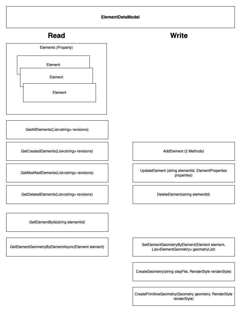
Element is a representation of an instance/entity within the Data Exchange. Elements are made up of a collection of Parameters and geometries and contain data about the Element such as units, transformation, and other metadata.
The ElementDataModel abstraction provides an Elements property, which is a list of all the elements that exist within the exchange up to that version. The ElementDataModel also contains information about deltas that have been received after the initial retrieval and can provide a list of elements that were created, modified, or deleted for a specific set of revisions. Additionally, the ElementDataModel offers the TopLevelElements property, which retrieves a list of the top-level elements within this Data Exchange.
Previously, Elements property was used to get the top-level elements and then called the GetFlattenedListOfElements method to obtain all the elements in the exchange. However, there is no longer a need to call any method to get all the elements present in the exchange, as the Elements property now retrieves all the elements in the exchange.
The GetElementGeometriesByElementsAsync method gets the geometries such as BRep, Mesh, and Primitive Geometry for a list of elements and is the preferred method to retrieve geometries due to performance optimizations.
Apart from the retrieval methods, the ElementDataModel abstraction also provides methods to create, modify, and delete elements from the list. The methods CreateGeometry and SetElementGeometry are used in creating and mapping geometry to the elements of a Data Exchange.
The ElementDataModel also provides the SetViewableWorldCoordinates method, which sets the orientation (the up, front, and north vectors) of the Forma (formerly ACC) viewable. The viewable is now generated automatically as part of the publish/sync process; the previous GenerateViewableAsync method has been removed. Call SetViewableWorldCoordinates before the publish/sync (SyncExchangeDataAsync) call.
    // Vector3d lives in the Autodesk.GeometryUtilities.PrimitivesAPI namespace.
    // If omitted, the defaults are UP = (0, 0, 1), Front = (0, -1, 0), North = (0, 1, 0).
    ElementDataModel.SetViewableWorldCoordinates(new ViewableWorldCoordinates()
    {
        UP = new Vector3d { X = 1, Y = 0, Z = 0 },
        Front = new Vector3d { X = 0, Y = 0, Z = 1 },
        North = new Vector3d { X = 0, Y = 0, Z = -1 }
    });
The SDK supports writing the following basic geometry data types:
- Brep/Mesh/IFC geometry through any generic file format, for example, BRep(STP), Mesh(OBJ), and IFC(IFC).
- Primitive geometry.
Adding Brep/Mesh/IFC Geometry to Elements of an Exchange
The following code samples demonstrate how you can add Brep/Mesh/IFC geometry to the elements of an exchange.
1. Creating the ElementDataModel Wrapper
First, create the ElementDataModel wrapper by calling the ElementDataModel.Create method and passing the instance of the exchange client (IClient).
2. Adding Elements to the Exchange
- Single-Level Elements: Call the AddElement method on the ElementDataModel to add a new element to the exchange. In the AddElement method, pass the id, name, category, family, and type of the element you want to add. This method is ideal when you want to add elements only at one level, that is, when there are no child elements.
- Hierarchical Elements: To add a child element to an existing element, call the AddElement method and pass the parent element as a parameter.
3. Creating Geometry
Create Geometry using the ElementDataModel.CreateGeometry method and pass an instance of GeometryProperties. The GeometryProperties constructor requires a file path (such as STEP, IFC, OBJ, etc.) and an instance of RenderStyle.
The RenderStyle instance holds the color details of the geometry in the Data Exchange. To apply the desired color to the geometry, create a RenderStyle instance with the required color and pass it, along with the file path, to the GeometryProperties constructor. This will apply the specified color to the geometry in the Data Exchange.
Note:
- The RenderStyle applies a single color to the entire body of the Data Exchange. If your body contains different colors and you pass the
RenderStyleinstance, the geometry will be overridden with the single color. The ideal scenario to use theRenderStyleinstance is when you want to apply a single color to your geometry. - If the RenderStyle instance is passed with a null value, the geometry will derive its color from the file specified in the first parameter of the GeometryProperties constructor. This file must contain the original color used to create the model of the Data Exchange, and the same color will then be applied to the geometry.
- For detailed information about controlling transparency and opacity in your geometry, including how Alpha and Transparency values work, see Controlling Geometry Opacity.
4. Code Samples
Adding Geometry to Single-Level Elements:
The following code sample shows how you can add geometry to the elements at one level (when child elements are not present)
        // Create an RGBA color: RGBA(Red, Green, Blue, Alpha)
        // Values range from 0-255 where 0 = none/transparent, 255 = full/opaque
        RGBA rgba = new RGBA(0, 0, 0, 255);  // Black color with full opacity

        // Create a RenderStyle: RenderStyle(name, color, transparency)
        // Transparency: 0.0 = fully transparent, 1.0 = fully opaque
        RenderStyle CommonRenderStyle = new RenderStyle("Name", rgba, 1.0);  // Solid material (fully opaque)

        // Create ElementDataModel wrapper
        var ExchangeDataWrapper = ElementDataModel.Create(Client);

        // Adds elements to the exchange (child elements are not present)
        var Element = ExchangeDataWrapper.AddElement("Id", "elementname");
        var category = ExchangeDataWrapper.Classify(Element, ClassificationSystem.Category, "category");
        var family = ExchangeDataWrapper.Classify(Element, ClassificationSystem.Family, "family", parent: category);
        var elementType = ExchangeDataWrapper.DefineType(system: "Type", name: "type", parent: family);
        ExchangeDataWrapper.SetType(Element, elementType);

        // Create Geometry
        var Path = "FilePath";
        var Geometry = ExchangeDataWrapper.CreateGeometry(new GeometryProperties(Path, CommonRenderStyle));

        // Map elements and geometry.
        var ElementGeometry = new List<ElementGeometry> { Geometry };
        ExchangeDataWrapper.SetElementGeometry(Element, ElementGeometry);
Adding Geometry to Hierarchical Elements:
The following code sample shows how you can add geometries to the elements at hierarchy (when parent and child elements are present)
        // Adds elements to the parent and child elements of the exchange

        // Add parent elements to the exchange.
        var RebarParentElement = ExchangeDataWrapper.AddElement("Id", "elementname");
        var rebarCategory = ExchangeDataWrapper.Classify(RebarParentElement, ClassificationSystem.Category, "category");
        var rebarFamily = ExchangeDataWrapper.Classify(RebarParentElement, ClassificationSystem.Family, "family", parent: rebarCategory);
        var rebarType = ExchangeDataWrapper.DefineType(system: "Type", name: "type", parent: rebarFamily);
        ExchangeDataWrapper.SetType(RebarParentElement, rebarType);

        // Add child elements to the exchange
        var RebarChildElement = ExchangeDataWrapper.AddElement($"Rebar-{i}-{j + 1}", $"Rebar-{i}-{j + 1}", RebarParentElement, childElementMatrix);

        // Create Geometry
        var Path = "FilePath";
        var Geometry = ExchangeDataWrapper.CreateGeometry(new GeometryProperties((Path, CommonRenderStyle));

        // Map elements and geometry
        var RebarElementGeometry = new List<ElementGeometry>();
        RebarElementGeometry.Add(Geometry);

        ExchangeDataWrapper.SetElementGeometry(RebarChildElement, RebarElementGeometry);
5. Creating Geometry using Mesh Object
The following steps will guide you through how to create mesh geometry.
- Create mesh object (complexMesh).
- Create an object called meshProperties of type GeometryProperties.
- The GeometryProperties constructor takes two arguments: complexMesh (the actual mesh object) and verifiableMeshName (a string serving as the name or identifier for the mesh).
- Create an object called meshGeometry using the CreateMeshGeometry method from the ElementDataModel class.
- The CreateMeshGeometry method takes the meshProperties object as an argument and generates the corresponding mesh geometry.
Code Sample for Mesh Geometry:
    var complexMesh = new Autodesk.GeometryUtilities.MeshAPI.Mesh()
    {
        // MeshColor: Color(Red, Green, Blue, Alpha) - values from 0.0 to 1.0
        // Alpha: 1.0 = fully opaque, 0.0 = fully transparent
        MeshColor = new Color(0.9f, 0.2f, 0.2f, 1.0f),  // Reddish mesh body color, fully opaque
        Vertices = new List<Vertex>
        {
            new Vertex(0.0, 0.0, 0.0),
            new Vertex(1.0, 0.0, 0.0),
            new Vertex(0.0, 1.0, 0.0),
            new Vertex(1.0, 1.0, 0.0),
        },
        Faces = new List<Face>
        {
            new Face()
            {
                Corners = new List<int> { 0, 1, 2 },
                Normals = new List<Normal>
                {
                    new Normal(0, 0, 1),
                    new Normal(0, 0, 1),
                    new Normal(0, 0, 1),
                },
                // FaceColor overrides MeshColor for this specific face
                FaceColor = new Color(0.2f, 0.2f, 0.9f, 1.0f),  // Blue face color, fully opaque
            },
        },
    };

    var elementDataModel = ElementDataModel.Create(Client);
    var element = elementDataModel.AddElement("1", "Name");
    var genericsCategory = elementDataModel.Classify(element, ClassificationSystem.Category, "Generics");
    var genericFamily = elementDataModel.Classify(element, ClassificationSystem.Family, "Generic", parent: genericsCategory);
    var nonGenericType = elementDataModel.DefineType(system: "Type", name: "Non-Generic Object", parent: genericFamily);
    elementDataModel.SetType(element, nonGenericType);

    // Create Mesh Geometry
    var meshProperties = new GeometryProperties(complexMesh, "verifiableMeshName");
    var meshGeometry = ElementDataModel.CreateMeshGeometry(meshProperties);

    // Map elements and geometry
    var geometries = new List<ElementGeometry> { meshGeometry };
    elementDataModel.SetElementGeometry(element, geometries);
In simple terms, these lines of code are used to take your existing mesh data, package it with a name, and then use that package to create a mesh geometry object that can be used within your application. This process helps in organizing and verifying the mesh data before it’s used in further operations or visualizations.
MeshAPIs Color Behaviour based on MeshColor and FaceColor:
The following outlines how MeshAPIs handle color assignments based on provided MeshColor and FaceColor properties.
MeshColor Only:
- Applied universally across the mesh.
- Returned color will be MeshColor (intended behavior).
MeshColor and FaceColor:
- MeshColor set to Gray.
- Faces without FaceColor inherit MeshColor.
- Faces with FaceColor retain their specific color.
No MeshColor:
- Defaults to Gray.
Adding Primitive Geometry to Elements of an Exchange
The SDK supports various primitive geometry types, from simple elements to complex geometries with large datasets. Supported geometries include:
- Standard primitives: Points, lines, arcs, circles, and other basic geometric elements
- Complex curves: Contour curves for topographic maps with thousands of segments per contour line
- Alignment geometries: Road or railway alignments with complex curve definitions
- Terrain surfaces: Large surface meshes with many vertices and faces
Generate a basic geometry using the Autodesk.GeometryPrimitive class.
Create Primitive Geometry using the ElementDataModel.CreatePrimitiveGeometry method. This method requires GeometryProperties instance which requires the primitive geometry definition and a RenderStyle instance.
If you want to add multiple primitive geometries to an element efficiently, it is recommended to use instance of GeometryContainer to create multiple primitive geometry.
Here is an example of how to add two lines to a single element using GeometryContainer:
        var lineGeomContainer = new GeometryContainer()
        {
            Curves = new CurveArray()
                {
                    new Line()
                    {
                        Position = new PrimitiveGeometry.Math.Point3d(0, 0, 0),
                        Direction = new PrimitiveGeometry.Math.Vector3d(1, 0, 0),
                        Range = new ParamRange(ParamRange.RangeType.Finite, -1000, 1000)
                    },
                    new Line()
                    {
                        Position = new PrimitiveGeometry.Math.Point3d(0, 0, 0),
                        Direction = new PrimitiveGeometry.Math.Vector3d(1, 0, 0),
                        Range = new ParamRange(ParamRange.RangeType.Finite, -1000, 1000)
                    },

                }
        };

        var element = ElementDataModel.AddElement("Id", "elementname");
        var primitiveCategory = ElementDataModel.Classify(element, ClassificationSystem.Category, "category");
        var primitiveFamily = ElementDataModel.Classify(element, ClassificationSystem.Family, "family", parent: primitiveCategory);
        var primitiveType = ElementDataModel.DefineType(system: "Type", name: "type", parent: primitiveFamily);
        ElementDataModel.SetType(element, primitiveType);

        // Create Geometry
        var elementPrimitiveGeometry = ElementDataModel.CreatePrimitiveGeometry(new GeometryProperties(primitivegeometry, RenderStyle));

        // Map elements and geometry.
        var elementGeometry = new List<ElementGeometry> { elementPrimitiveGeometry };
        ElementDataModel.SetElementGeometry(element, elementGeometry);
Apply Transformations to elements
You can apply a transformation to a Data Exchange element by passing a Transformation to the ElementDataModel.AddElement method.
    var transformation = new Transformation
    {
        Matrix = new Matrix4d(new float[] {
            1,
            0,
            0,
            0,
            0,
            1,
            0,
            0,
            0,
            0,
            1,
            0,
            0,
            0,
            0,
            1})
    };
    var element = ElementDataModel.AddElement("Id", "Name_For_Element_Propeties", transformation: transformation);
    var transformCategory = ElementDataModel.Classify(element, ClassificationSystem.Category, "category");
    var transformFamily = ElementDataModel.Classify(element, ClassificationSystem.Family, "family", parent: transformCategory);
    var transformType = ElementDataModel.DefineType(system: "Type", name: "type", parent: transformFamily);
    ElementDataModel.SetType(element, transformType);
Set Units to elements
The default values of LengthUnit and DisplayLengthUnit of the data exchange element and geometry are set to feet if not set explicitly.
Important: It is recommended that you set the LengthUnit to match the host application’s document unit. For example, if you create a model in the host application in millimeter and create a data exchange without setting the length unit explicitly, then the data exchange will use the default units of measurement, which is ‘feet’, leading to a mismatch of units. This may lead to inaccurate data, unless you perform scaling of the geometry during both the creation and loading of the exchange to correct the values.
To set units on the element, pass lengthUnit and displayLengthUnit to AddElement as shown in the following code sample.
    var element = ElementDataModel.AddElement(
        "Id",
        "elementname",
        lengthUnit: UnitFactory.MilliMeter,
        displayLengthUnit: UnitFactory.MilliMeter);
To set units on the element geometry use the GeometryProperties object as shown in the following code sample.
    // Set units using GeometryProperties
    var Geometry = ElementDataModel.CreateGeometry(new GeometryProperties(Path, RenderStyle)
    {
        LengthUnit = UnitFactory.MilliMeter,
        DisplayLengthUnit = UnitFactory.MilliMeter,
        DisplayAngleUnit = UnitFactory.Radian
    });
The Autodesk.DataExchange.SchemaObjects.Units.UnitFactory includes commonly supported units such as feet, meter, and inches.
Add Parameters to elements
There are two general types of parameters that can be added to an element:
- Built-In Parameters: Generate a ParameterDefinition instance using the static ParameterDefinition.Create method, which takes an Autodesk.Parameters.Parameter enum and a ParameterDataType enum as inputs. The specific type of parameter instance is determined by the ParameterDataType provided. After creating the parameter instance, assign a value to it.
- Custom Parameters: Use the static ParameterDefinition.Create method to generate a ParameterDefinition instance, where the method requires a string schemaId and an enum ParameterDataType as inputs. The nature of the parameter instance produced depends upon the provided ParameterDataType. Use IsCustomParameter=true instead of IsForceCheckFSSSChemaPresent which is deprecated in order to mark this parameter as custom parameter. Subsequently, assign a value to the recently instantiated parameter instance.
To create the schemaId, you will require the schemaNamespace. When an exchange container is first created using the IClient.CreateExchangeAsync method, it returns an ExchangeDetails object, which contains a property called schemaNamespace. This schemaNamespace can be used to produce the schema ID. As a best practice, we should ideally avoid using ForgeParametersCLR or ForgeUnitsCLR directly for parameter processing (for example, create, update, etc.) to minimize the risk of breaking changes caused by updates to these assemblies.
Create the parameter with the help of Element.CreateInstanceParameterAsync method and pass the instance of CustomParameter.
Important: When creating custom parameters, always set the Name property.
    // Instance parameters
    // Built-In Parameters
    var Parameter = ParameterDefinition.Create(Autodesk.Parameters.Parameter.<Built-In-Parameter>, ParameterDataType);
    ((<Cast-As-Per-DataType>)Parameter).Value = data;
    element.CreateInstanceParameterAsync(Parameter);

    // Custom Parameters
    var SchemaId = "exchange.parameter." + schemaNamespace + ":<parameterTypeSchema>";
    ParameterDefinition CustomParameter = ParameterDefinition.Create(SchemaId, ParameterDataType);
    CustomParameter.Name =;
    CustomParameter.SampleText =;
    CustomParameter.Description =;
    CustomParameter.ReadOnly =;
    customParameterFloat.IsCustomParameter = true;
    CustomParameter.GroupID = Group.General.DisplayName();
    ((<Cast-As-Per-DataType>)CustomParameter).Value = data;
    element.CreateInstanceParameterAsync(CustomParameter);
Create the parameter with the help of ElementDataModel.CreateTypeParameterAsync method and pass the instance of CustomParameter.
Type parameters are parameters that apply to all elements of a specific type. Modifying a type parameter will apply that change to all elements that belong to that type. This simplifies the management of common properties based on a common type.
To create a type parameter, first ensure that the “type” has been defined. A type is automatically defined when an element specifies a type during its creation. Once the following line in the code sample is executed, the “MyType” type is defined and can be used to set type parameters.
var Element = model.AddElement("<Id>", "<elementname>");
var category = model.Classify(Element, ClassificationSystem.Category, "<category>");
var family = model.Classify(Element, ClassificationSystem.Family, "<family>", parent: category);
var myType = model.DefineType(system: "Type", name: "MyType", parent: family);
model.SetType(Element, myType);
At this point, other elements with the same type can also be created. All of these elements will share the same type parameters.
To create a type parameter, use the ElementDataModel.CreateTypeParameterAsync method by passing in the “MyType” string and the parameter to set. This differs from instance parameters, where the parameter is set to the individual element. Type parameters, on the other hand, are shared across all elements of that type. An element’s TypeParameters property lists all the type parameters associated with that element.
    // Instance parameters
    // Built-In Parameters
    var Parameter = ParameterDefinition.Create(parameterType, ParameterDataType.Int64);
    (Int64ParameterDefinition)Parameter).Value = 100;
    ElementDataModel.CreateTypeParameterAsync("MyType", Parameter);

    // Custom Parameters
    var SchemaId = "exchange.parameter." + schemaNamespace + ":<parameterTypeSchema>";
    ParameterDefinition CustomParameter = ParameterDefinition.Create(SchemaId, ParameterDataType);
    CustomParameter.Name =;
    CustomParameter.SampleText =;
    CustomParameter.Description =;
    CustomParameter.ReadOnly =;
    customParameterFloat.IsCustomParameter = true;
    CustomParameter.GroupID = Group.General.DisplayName();
    ((<Cast-As-Per-DataType>)CustomParameter).Value = data;
    ElementDataModel.CreateTypeParameterAsync("Generic Object",CustomParameter);
ParameterDefinition types as per parameter data type:
- BoolParameterDefinition -> Bool
- Int64ParameterDefinition -> int64
- MeasurableParameterDefinition -> float
- StringParameterDefinition -> string
Add Parameters to Geometry
Attach parameters directly to geometry objects for Navisworks export and Rhino interoperability. When you export to Navisworks, each geometry piece displays its specific properties (material, thickness, manufacturer) rather than just element-level properties.
When to Use Geometry Parameters
Use geometry parameters when properties belong to specific geometry pieces rather than the element as a whole:
- Geometry parameters: Material per piece, thickness per component, finish per surface
- Element parameters: Element name, category, location, fire rating
For example, a door element might have:
- Element parameter:
FireRating = "90 minutes" - Frame geometry parameter:
Material = "Steel" - Panel geometry parameter:
Material = "Glass"
Create Geometry Parameters
Add parameters to geometry using the CreateParameter method:
// Create geometry
var geometry = ElementDataModel.CreateFileGeometry(
    filePath: "component.stp",
    format: GeometryFormat.Step
);

// Add parameters to the geometry
await geometry.CreateParameter(new Parameter("Material", "Steel"));
await geometry.CreateParameter(new Parameter("Thickness", 5.5));
await geometry.CreateParameter(new Parameter("Finish", "Galvanized"));

// Add geometry to element
element.AddGeometry(geometry);
Multiple Geometries with Different Parameters
var doorElement = ElementDataModel.AddElement("door-001", "Front Door");
var doorCategory = ElementDataModel.Classify(doorElement, ClassificationSystem.Category, "Doors");
var doorFamily = ElementDataModel.Classify(doorElement, ClassificationSystem.Family, "Single", parent: doorCategory);
var doorType = ElementDataModel.DefineType(system: "Type", name: "Standard", parent: doorFamily);
ElementDataModel.SetType(doorElement, doorType);

// Frame geometry with its own parameters
var frameGeometry = ElementDataModel.CreateFileGeometry(
    filePath: "door-frame.stp",
    format: GeometryFormat.Step
);
await frameGeometry.CreateParameter(new Parameter("Material", "Wood"));
await frameGeometry.CreateParameter(new Parameter("Finish", "Stained"));
doorElement.AddGeometry(frameGeometry);

// Panel geometry with different parameters
var panelGeometry = ElementDataModel.CreateFileGeometry(
    filePath: "door-panel.stp",
    format: GeometryFormat.Step
);
await panelGeometry.CreateParameter(new Parameter("Material", "Glass"));
await panelGeometry.CreateParameter(new Parameter("Type", "Tempered"));
doorElement.AddGeometry(panelGeometry);
Custom Geometry Parameters
Create custom parameters with full metadata:
var schemaId = "exchange.parameter.custom:manufacturer";
var customParam = ParameterDefinition.Create(schemaId, ParameterDataType.String);

customParam.Name = "Manufacturer";
customParam.Description = "Component manufacturer name";
customParam.IsCustomParameter = true;
customParam.GroupID = Group.General.DisplayName();

((StringParameterDefinition)customParam).Value = "ACME Corp";

await geometry.CreateParameter(customParam);
For comprehensive information on working with geometry parameters, including reading, updating, and deleting parameters, see Working with Geometry Parameters.
Related operations:
- Retrieve Parameters from Geometry - Read geometry parameters
- Update Geometry Parameters - Modify parameter values
- Delete Geometry Parameters - Remove parameters
Publish/Sync
In the preceding steps, we have already created the ElementDataModel and added geometry and parameters into it locally. To sync or update this data to the Data Exchange make a call to the SyncExchangeDataAsync method on the IClient interface.
    var ExchangeIdentifier = new DataExchangeIdentifier
    {
     CollectionId = CollectionID,
     ExchangeId = ExchangeID,
     HubId = hubId
    };

    var ExchangeData = ElementDataModel.ExchangeData;
    await IClient.SyncExchangeDataAsync(ExchangeIdentifier, ExchangeData);
Exchange creation progress
The SDK reports progress during exchange creation in four stages. Each stage updates progress as work completes.
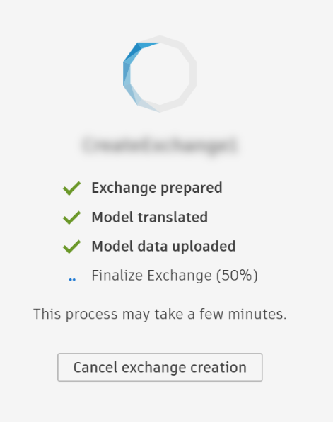
Stage 1: Prepare exchange
The SDK performs these substeps:
- Retrieves the region
- Retrieves the collection
- Creates the exchange container
- Extracts metadata from the response
Progress updates by 25% after each substep completes.
Stage 2: Translate model
The SDK translates geometry assets into internal format using batches of 5,000 assets. Progress updates after each batch completes.
Example: An exchange with 12,000 geometry assets processes in three batches (5,000 + 5,000 + 2,000). Each batch updates progress by 33%.
Stage 3: Upload model data
The SDK combines geometries into binary packs (maximum 100 MB each). Hundreds of geometries can combine into one binary pack. Progress updates after each binary pack uploads.
Example: An exchange that creates two binary packs updates progress by 50% after each upload completes.
Stage 4: Finalize exchange
The SDK completes these substeps:
- Sends fulfillment sync requests (count varies by exchange size)
- Generates the viewable
- Uploads the viewable
Progress updates after each substep completes.
Example: An exchange that requires three fulfillment sync requests processes five total substeps (3 sync requests + viewable generation + viewable upload). Each substep updates progress by 20%.
Viewable generation
After you sync the data to the Data Exchange, the viewable (a visual representation of the data) is generated automatically as part of the sync process. You no longer call a method to start it. To set the orientation of the generated viewable, call SetViewableWorldCoordinates before the publish/sync (SyncExchangeDataAsync) call, as shown in the SetViewableWorldCoordinates example earlier in this guide.